Wind Harmonics and Vibration

    LIGHT STANDARD DESIGN

    Light standards (pole) are designed to accommodate certain specific environmental, load and aesthetic requirements. Various standards, guidelines, and codes govern their use like the American Association of State Highway and Transportation Officials (AASHTO), American National Standards Institute (ANSI) and many local building codes. These standards and codes are based on theoretical analysis, research and current industry practice. The standards and codes take into account direct wind pressures on the pole and luminaire; bending, shear, axial and torsional stresses; secondary moment effects (the pole and fixture being off center of the pole base when the wind deflects the pole) and the effect of heat on the base material in the area adjacent to the weld. Pole design required consideration of field conditions. All variables must be taken into consideration with selecting the pole.

    Poles, which perform satisfactory in many installations all over the country, may experience destruction vibration for no apparent reason at a select location. Typically poles are designed or selected based on the 50-year mean wind map found in AASHTO, ANSI or local building codes. These indicate a minimum wind load of 70+ mph, but do not take into account certain wind conditions that can create damaging vibration. Vibration is a local site-specific condition, which is many times overlooked by those selecting a pole because it is difficult to accurately predict. Vibration can be caused by steady relatively low speed wind (10-30 mph), topography or the structure the pole is mounted to can also have impact. Studies indicate that the natural turbulence of the air stream at higher wind velocities, above 30 mph, inhibit vibration. Destructive vibration is not an indication of substandard material, workmanship or design of the pole.

    VIBRATIONS

    There are two common types of vibration observed in poles.

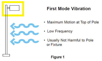
    First mode Vibration sometimes referred to as sway, in which the maximum deflection occurs at the top of the pole, the deflection off center is not equal from side to side and it occurs at a low frequency, approximately once cycle per second (Figure 1). This from of vibration is usually not harmful to the pole or luminaire.

    First Mode Vibration

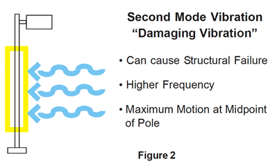
    Second mode vibration can be the most damaging form of vibration and occurs approximately at the midpoint of the pole with the deflection off center equal from side to side (Figure 2). It is a higher frequency; typically three to six cycles per second.

    Second Mode Vibration

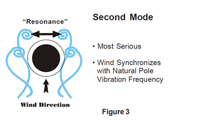
    Second mode vibration occurs when the wind synchronizes with the natural pole vibration frequency. This is known as resonance (Figure 3). As the steady low level wind moves past the pole, vortices are shed alternately from either side of the structural shaft causing displacement oscillations in a direction perpendicular to that of the wind. Vortices are a swirling motion of pattern of the wind. The most serious situation arises when the vortex-shedding frequency synchronizes with the natural period of vibration in the pole, which can ultimately fatigue the pole to structural failure.

    Second Mode - Resonance

    CONTRIBUTING VARIABLES

    Each job site has different variable that may contribute to structural fatigue vibration. These pole variables should be taken into consideration, along with environmental and structural factors, to determine if the potential for vibration exists.

    • Total Load (EPA) and Shaft Length: Light loading, less than 2.0 EPA and shaft length at or above 25 feet. These two factors when combined can be key ingredients for destructive vibration.
    • Shape: Straight Square Poles have historically experienced more effects of destructive vibration over other shapes, but no shape is exempt.
    • Installation Procedures: Poles are designed to carry a load. Never install a pole without the intended luminaire being installed.

    ENVIRONMENTAL & STRUCTURAL FACTORS

    The presence of special wind conditions in an area can be attributed to various factors. There can also be factors generated by the structure that the pole is mounted to. These factors can create the destructive conditions over an entire site or can be isolated affecting only specific pole locations on the site. If the following factors are present, be aware the conditions may exist for structural fatigue vibration to occur.

    • Parking Deck Installation: Influences from surrounding structures and transferred vibration generated by moving vehicles
    • Near or at airports: Little or no objects to break the wind currents and the presence of turbulence created by aircraft.
    • Bridge Installation: Little or no objects to break the wind currents and the transfer of vibration generated by moving vehicles.
    • Mountain Foothill Areas: Air currents traveling from the higher elevations can create steady damaging winds.
    • Large Expanse of Flat Ground: In tandem with little or no structures, the wind currents will not be disrupted which sets up the possibility for low steady winds and destructive vibration.
    • Steady Low Level Winds: The upper mid-west and plains states have shown this trend

    Note: This is not a complete list, other factors can influence the effects of wind.

    POTENTIAL SOLUTIONS

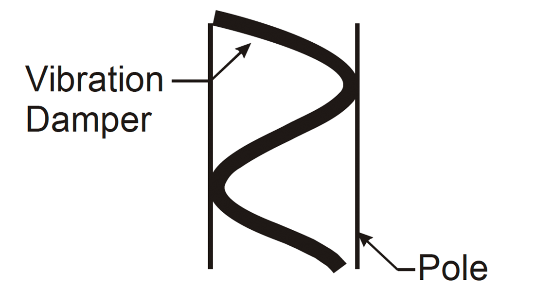
    To minimize the effects of structural fatigue vibration, a device can be factory or field installed to absorb or dampen the vibration. Another option is to initially design the pole to withstand the fatigue effects if it is in an area with historical problems

    The poles designed can be based on the infinite fatigue life of the materials. This option is more expensive and may not meet the budget restraints of a project, consult factory for assistance.

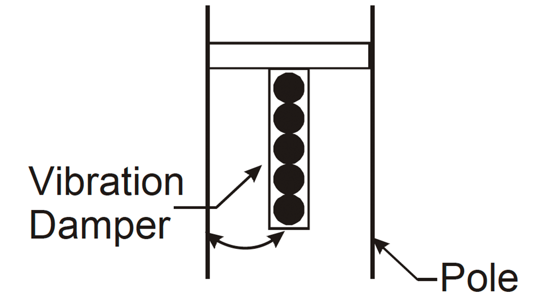
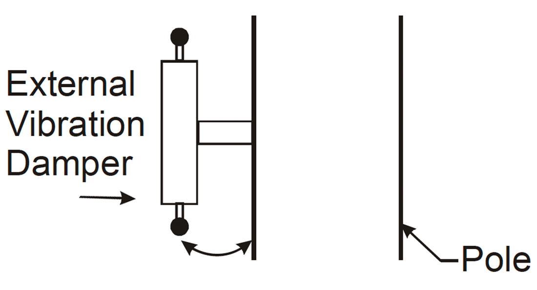
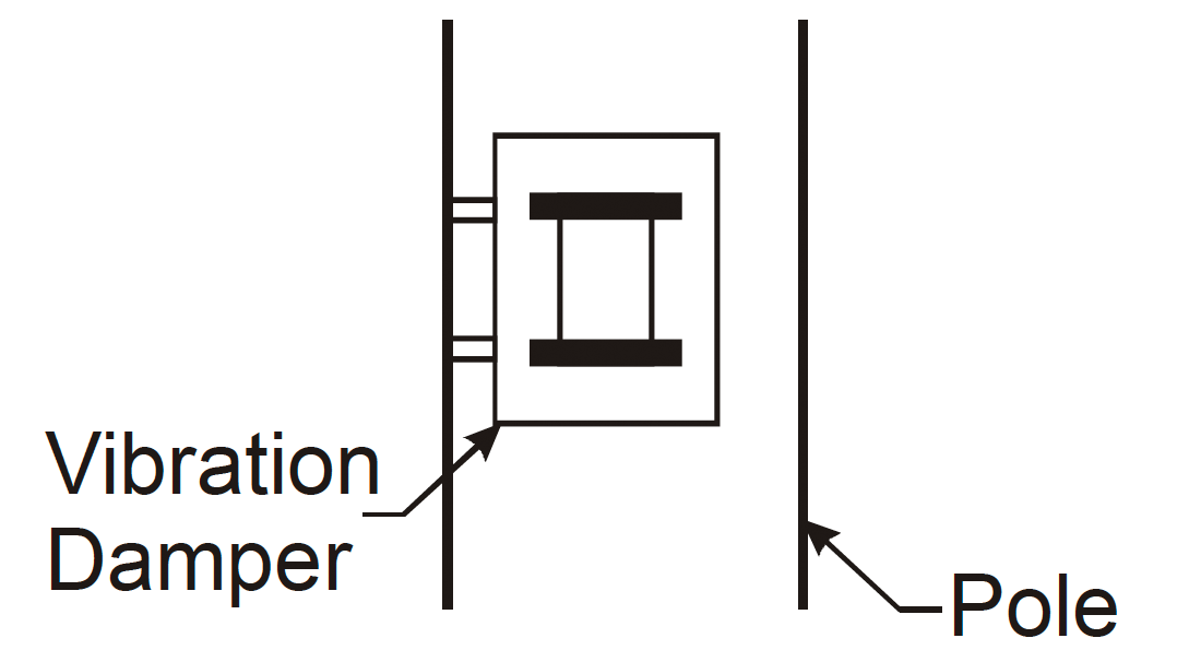
    A more economical option is the use of factory or field installable damping devices. The field installable version is more economical than the factory installable damper and provides the flexibility of installation where and when necessary, see below.

    Snake Vibration Damper

    Field Installable

    "Snake" - Plastic flexible tube, which contacts the sides of the shaft and disrupts the vibration.
    Chain Vibration Damper

    Field Installable

    “Chain” - Swaying motion of damper will hit inside of shaft and disrupt vibration. Can cause objectional noise.
    Stockbridge Vibration Damper

    Field Installable

    “Stockbridge Damper” - Ends of damper move in the opposite direction of the shaft and disrupt vibration.
    Canister Vibration Damper

    Factory Installed

    “Canister” - Internal disks move in the opposite direction of the shaft and disrupts vibration.

    Another option is the shape. Even though all pole types can experience vibration, straight square shafts seem to be more susceptible. Round tapered shafts tend to disrupt the vortex- shedding resonance state. The use of a vibration damper in conjunction with the round tapered design may be the best solution, but is not a guarantee to prevent destructive vibration.

    MAINTENANCE

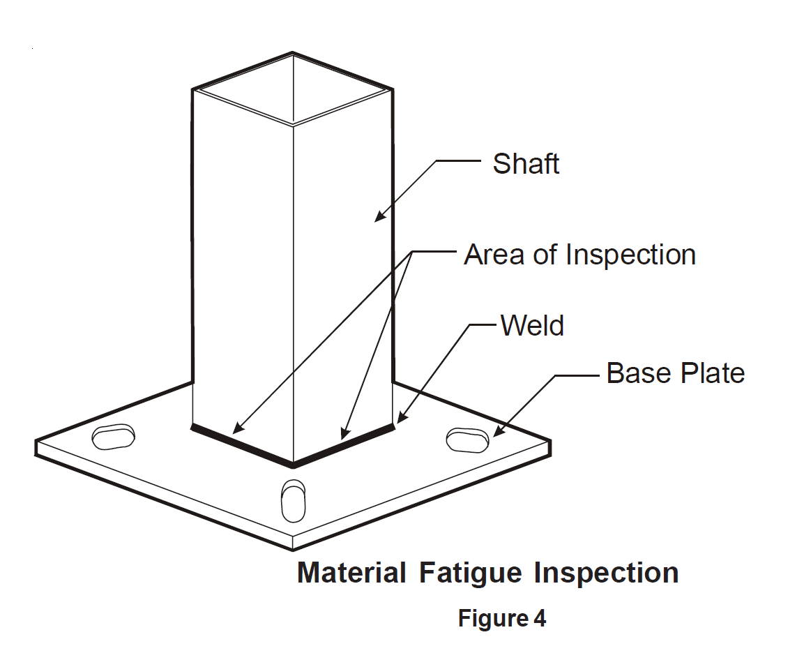
    Poles should be included in a regular maintenance schedule like any other equipment in a facility. Every three months is a good rule of thumb. Inspecting for the effects of vibration is a very important element because if it does exist, the pole can fall in a relatively short period of time. The results can be catastrophic from luminaire failure to complete structural failure. Early signs of vibration can be visibly observed, detected by the presence of noise (humming) in the pole, loosening of attached luminaire components like sockets and lamps and short lamp life. If any of these signs exist, further inspection should be performed in the area where the shaft connects to the base plate. Look for signs of shaft material fatigue just above the entire weld in the form of hairline cracks (Figure 4).

    Material Fatigue Inspection

    Some of the processes are:

    • Visual Inspection - Typically rust will be apparent in the area of the fatigue on steel poles.
    • Red die penetration test - Check for weld penetration and reveals fatigue cracks. This will work for aluminum or steel that does not show signs of rust.
    • X-ray - This requires that the pole be sent to a lab which is time consuming and expensive, but necessary on occasion.

    It is recommended that a licensed structural engineer be consulted to verify the problem. If material fatigue exists, the effected standards should be taken down immediately and damping devices installed in the remaining standards as soon as possible after a complete inspection. Even after the corrective measures have been performed, future inspections for the signs of vibration is a must. The information contained in this document is based on historical data and should be utilized to minimize the potential of structural fatigue occurring. Site specific variables may exist that have not been historically identified. The variables that have been identified can only approximate the potential for structural fatigue.

    The information contained in this document is based on historical data and should be utilized to minimize the potential of structural fatigue occurring. Site specific variables may exist that have not been historically identified. The variables that have been identified can only approximate the potential for structural fatigue.

    Wind Induced Vibrations on Light

    By Pete Manis, P.E., and Wes Jones, P.E.
     
    The authors were recently involved in a project for which site work consisted of curb and gutter, sidewalks, parking lot paving, and light poles with foundations in the parking lot and along the roadway. Approximately five months prior to ribbon cutting, the client noticed that nearly all of the light poles were swaying considerably under wind velocities of approximately 17 to 28 mph, with gusts up to 46 mph. Figure 1 illustrates the observed light pole movement, which had a magnitude of approximately 8 to 12 inches.
     
    The very next day, the client discovered one of the light poles on the ground, with what appeared to be fatigue cracking at the weld between the light pole base plate and the pole itself (Figure 2). The client took down the remaining poles to prevent further failures. Fortunately, there were no injuries associated with the light pole failure, since this event occurred during the night when the construction crew was not present.
     
    Review of the light pole submittal revealed that the subcontractor had proposed a different size and type of pole than what had been originally selected – a 30 foot tall, 6 inch square aluminum pole. Instead, the subcontractor proposed a 30 foot tall, 4 inch square steel pole, which was approved since the 4 inch pole more than adequately met the performance specification according to the manufacturer's literature.
     
    Consultations with the light pole supplier and manufacturer indicated that the failure of the light pole was "most likely" due to wind induced harmonic resonance of the light pole, and subsequent fatigue cracking of the weld between the base plate and the pole. The light pole manufacturer responded to a request for replacement light poles by saying that its standard one year warranty does not cover "naturally occurring harmonic vibration light pole failures". Additional calls to various light pole manufacturers revealed that none of them warrant failure due to harmonic vibration.
     
    It is important to note that the failed light pole met all of the manufacturer's requirements, and had been properly selected and installed based on their criteria. Many light pole manufacturers publish wind speed maps and light pole selection criteria for their products.
            
     
    The following is a common light pole selection procedure:
     
    1) Select the light fixture, and obtain its effective projected area (EPA) and weight. The EPA is the area that is loaded by wind. This information is located on the fixture cut sheet.
     
    2) Determine the number of light fixtures and any special mounting methods (arm or bracket) to be installed on the pole. Obtain the EPA and weight for any arms or brackets from the corresponding cut sheets.
     
    3) Add up the EPA and the weights of all fixtures, arms, and brackets.
     
    4) Select the design wind speed for the project location from the light pole manufacturer's wind map. Typically, this is a fastest mile wind speed, which is different from the current building code values for a 3 second gust. Tables exist for converting between the two.
     
    5) Select a pole, and compare both the EPA and weights of the fixture with the allowable EPA and weights for that specific pole. If the actual EPA and weights of the fixtures are less than the allowable EPA and maximum weight listed on the pole cut sheet, then the pole meets the requirements.

    Consequently, the use of shorter light poles with multiple light fixtures will generally reduce the chances of resonance. The shorter length provides a more rigid structure, and having more fixtures at the top equates to greater wind loading. This wind loading and the fixture weight at the top act as dampers to reduce resonant movement of the pole.
    Additionally, although no shape is exempt from wind induced resonance, it has been noted that round (or octagonal) tapered light poles are less susceptible to it than square ones. The natural frequency of a tapered light pole varies along its length, which makes it less likely to develop overall resonance from a constant wind. This is evident in the common types of poles used for highway lighting, flagpoles, and traffic control/signage structures.

    Wind Induced Vibrations

     In the case of this project, the light poles met these criteria and yet still failed under the destructive effects of vibration under modest wind speeds; the design wind speed was 80 mph (fastest mile). In fact, when the wind speed matches the natural frequency of the light pole, there will "always" be resonance as a result. This will lead to fatigue cracking of the weld at the base plate to pole interface. Only in certain circumstances are light poles designed to resist fatigue, according to AASHTO Standard Specifications for Structural Supports for Highway Signs, Luminaires and Traffic Signals – specific "high level" lighting structures, along with overhead cantilevered traffic signal and sign structures. AASHTO indicates that common light poles do not normally exhibit fatigue problems, but as our example indicates, such failures can occur.
     
    Rather than investing time and energy into fatigue analysis and mitigation in common light poles, a cost effective approach is to minimize the probability of resonance by eliminating characteristics that enhance resonance. Two contributing factors to light pole resonance are height and fixture arrangement. One pole manufacturer indicates that light poles with a fixture EPA of less than 2.0 (very few fixtures) at a height of 25 feet or greater have an increased probability of resonance. While such a slender light pole can withstand the maximum design wind speeds, which generally are above 70 mph, it is susceptible to wind induced vibration, which typically occurs around 20 - 40 mph.
     
    As an example, consider the vibration of a flagpole exposed to wind. When there is no flag on the pole, it is quite common to hear cables "banging" against the pole. This is due to movement or vibration of the pole. However, when there is a flag at the top of the pole, the wind loading applied to the flag acts to dampen the resonant movement of the pole, eliminating the "banging" sound. (Incidentally, flagpoles have a different foundation anchoring system that typically does not include a base plate or welds. See the NAAMM Guide Specifications for Design of Metal Flagpoles for more information on flagpole design).
     
    Further, the geographic location of a light pole may also contribute to the steady state, low wind speeds that result in light pole resonance. It has been noted that features such as unobstructed flat land or low level mountains, where wind can be channeled through an area, may contribute to light pole resonance, as well as turbulence created by aircraft or vehicular traffic.
     
    Many light pole manufacturers have attempted to minimize the problem of light pole resonance by offering factory or field installed dampers. A damper will essentially change the natural frequency of the light pole such that it will not coincide with a specific wind speed range. In many cases, these dampers are hanging weights that are installed either on the surface of the light pole or inside it. Dampers are not a cure all for resonance, because they only change the range of wind speeds that can cause wind induced resonance.
     
    Based on the information above, the following recommendations have been collected from various light pole manufacturers' literature and should be considered to reduce the probability of wind induced resonance:
    1) Use round (preferably tapered) light poles less than 25 feet tall, with a 6 inch minimum diameter.
    2) Use a minimum of two fixtures per pole to provide some weight at the top to help dampen the light pole.
    3) Include in the pole specifications a requirement for factory – or field installed vibration dampers to be provided by the light pole manufacturer.
    4) Contact the light pole manufacturer when there are site specific concerns that should be considered during light pole design.
    5) Provide specific wind loading information in the documents, and indicate whether wind loading is based on a 3 second gust or fastest mile wind speed.
     
    Periodic maintenance and inspection of a light pole can help determine if wind induced vibration is a concern. Items to be inspected include the weld between the base plate and the light pole shaft and loosening or damage of the light fixture, as well as frequent lamp replacement. The client should be notified of the potential problem – possibly as part of a specifications required O&M manual – and a maintenance plan should be implemented.
    Light Pole Design
     
    Pole design requires consideration of field conditions such as wind speed (sustained/gusts), pole height, appendages and local conditions. Vibration is a local, site specific condition that may be overlooked by those selecting a pole because it is difficult to predict accurately. Poles which perform satisfactory in many installations across the country, in select locations, may experience destructive vibration for no apparent reason. Typically, poles are designed or selected based on the 50 year maximum wind velocity map found in AASHTO (American Association of State Highway and Transportation Officials). The standards and codes take into account direct wind pressures on the pole and luminaire; bending, shear, axial and torsional stresses; secondary moment effects (the pole and fixture being off center of the pole base when the wind deflects the pole) and the effect of heat on the base material in the area adjacent to the weld.
     
    Second mode vibrations can be caused by steady, relatively low speed wind (10 - 30 mph), by typography and by the structure to which the pole is mounted. Destructive vibration is not an indication of substandard material, workmanship or design of pole.
     
    Variables
     
    Each job site has different variables that may contribute to structural fatigue vibration. These pole variables should be taken into consideration, along with environmental and structural factors, to determine if the potential for vibration exists.
     
    Total load (EPA) and shaft length: Light loading, less than 2.0 EPA and shaft length at or above 25 feet. These two factors when combined can be key ingredients for destructive vibration.
     
    Shape: Straight Square Poles historically experience more effects of destructive vibration than other shapes, but no shape is exempt.
     
    Installation procedures: Poles are designed to carry a load and a pole cannot be installed before the luminaire is mounted. Never install a pole without the intended luminaire in place.
     
    Parking deck installation: Influences from surrounding structures and transferred vibration generated by moving vehicles.
     
    Near or at airports: Little or no objects to break the wind currents and the presence of turbulence created by aircraft.
    Vibration Modes
     
    Two common types of vibrations are observed in poles.
     
        1. First Mode Vibration: Sometimes referred to as sway, the maximum deflection occurs at the top of the pole. First mode oscillation typically occurs at a low frequency, approximately one cycle per second. Normal deflection of this shape usually is not harmful to the pole or luminaire, but first mode oscillating vibration will cause damage.
     
        2. Second Mode Vibration: Can be the most damaging form of vibration. It occurs approximately at the midpoint of the pole with the deflection off center equal from side to side. It is at a higher frequency; typically three to six cycles per second. Second mode vibration occurs when the wind synchronizes with the natural pole frequency. This is known as resonance. As the steady low level wind moves past the pole, vortices are shed alternately from either side of the structural shaft causing displacement oscillations in a direction perpendicular to that of the wind. Vortices are a swirling motion or pattern of the wind. The most serious situation arises when the vortex shedding frequency synchronizes with the natural period of vibration in the pole, which can ultimately fatigue the pole to structural failure.

    Field Installed Vibration Damper

    CAUTION: Before installation, power to the pole should be disconnected and an inspection made by an authorized electrician to ensure that the wiring and electrical components will allow for easy and safe insertion of the dampening system. Items such as a terminal block and fuse assemblies may require temporary removal.
     
    Installation Procedure:
     
        1. Remove the hand hole cover from the pole in which the damper is to be inserted.
     
        2. Insert one end of the damper into the pole through the hand hole opening
     
        3. Push the damper up into the pole.
     
        4. When the damper is fully inserted it will slip down and rest on the foundation, it is IMPORTANT that the damper be lowered slowly, with the bottom end held tight to one side, in order to prevent damage to the electrical components.
     
        5. Return the hand hole cover to the pole.
     
    Caution: Electrical inspections again required to check the system and verify operation.