

Pole Selection Process
Summary:
Selecting the appropriate combination of shaft diameter and wall thickness for a specified pole type and height, to prevent overstressing caused by the loading forces of mounted items, can also be referred to as “sizing a pole”. All pole assemblies require this evaluation of size to loading prior to ordering and installing. You may ask, why do we need to “size” every pole? Simply put, to ensure that the structural integrity of the complete pole assembly is not compromised in location specific wind conditions. If a pole is overstressed from excessive loading forces, both dynamic loads (effective projected area - EPAft²) and static loads (weight), this can cause a safety hazard if the pole were to fail and fall.
The process of sizing a pole combines the desired pole height, all the mounted item’s EPAft², weights and the anticipated maximum wind speed based on design criteria.
The total EPAft² and weight of these items MUST NOT exceed the maximums listed for the specified pole at the anticipated maximum wind speed based on the design criteria. If either exceeds, then the pole shaft diameter or wall thickness must be increased to one that is suitable for both.
General Pole Selection Procedure:
Step 1. Select the light fixture and other mounted items. Decide how many of each will be mounted per pole. Determine the appropriate mounting method for the fixture; options include drill, tenon, arm/bracket, and band mounting.
Step 2. Determine the EPAft² and the weights for each mounted item. Acuity Brands’ luminaires will have this listed on the specification sheets.
Step 3. Add together the EPAft² of all mounted items and arms/brackets. If you have more than 1 luminaire and/or arm, then multiply their EPAft² by the total quantity per pole.*
Step 4. Add together the weight of all mounted items and arms/brackets. If you have more than 1 luminaire and/or arm, then multiply their weight by the total quantity per pole.*
* When summating the loading forces on your pole to find the mounted item’s total weight and EPAft², you must include all the below. This information can be located on the item’s specification sheet.
- Luminaires
- Cameras
- Signs
- Speakers
- Brackets
- Banners
- Cables and catenary systems
- Lightning rods
- Any other “decoration”
Step 5. Determine the building design criteria for your job site. Design criteria is a set of standards and calculations developed using ASCE wind maps, engineering design experience, and testing.
The criteria is created by governing bodies such as the American Association of State Highway and Transportation Officials (AASHTO), IBC (International Building Code) and FBC (Florida Building Code). Design Criteria can be found in the project’s spec. It is chosen most often based on:
- The job site’s location
- Governing bodies
- Local and state jurisdictions
- Contractors
Step 6. Consult the appropriate ASCE wind map based on the job site’s design criteria to determine the anticipated maximum wind speed for your location.
Resources:
ASCE wind map link: https://hazards.atcouncil.org/
More Wind maps can be found Here.
- Commercial Criteria
- AASHTO 1994
- AASHTO 2009
- AASHTO 2013
- IBC 2009
- FBC 2010
- AASHTO 2015
- IBC 2015
Step 7. Select the material (steel or aluminum) and shape (square or round, tapered or straight) of the desired pole. Review the “Technical Data” tables on the pole’s specification sheet.
- Choose the table based on the design criteria. Table one represents AASHTO 1994 using ASCE 7-93 wind map. Table two represents AASHTO 2013 using ASCE 7-05 wind map.
- Find the desired nominal mounting height in the second column.
- Move to the right until you locate the column representing your location’s windspeed. Verify that total EPAft² and weights summated in steps 3 and 4, do not exceed the maximums listed for the desired pole.
- If both the summated EPAft² and weights do not exceed the value for which the pole is rated, you have selected the correct pole. If, however, either one of those numbers exceeds the maximum rated values, review the next larger pole shaft diameter and/or wall thickness until a combination is found that is equal to or greater than the summated EPAft² and weights.
Example:
Customer wants to install a square straight steel, 20ft pole in Houston, TX and will be drill mounting a quantity of 2, DSX2’s on to the pole. The required building design criteria has been determined to be AAHSTO 2013.
Step 1. Light fixture: Quantity of 2 DSX2. Mounting method: drill mounted.
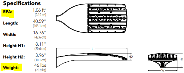
Step 2. DSX2 EPAft² = 1.06 ft². DSX2 Weight = 46lbs.
Step 3. 1.06 ft² x 2 = 2.12ft²
tep 4. 46lbs x 2 = 92lbs
Step 5. Design Criteria was determined to be AASHTO 2013
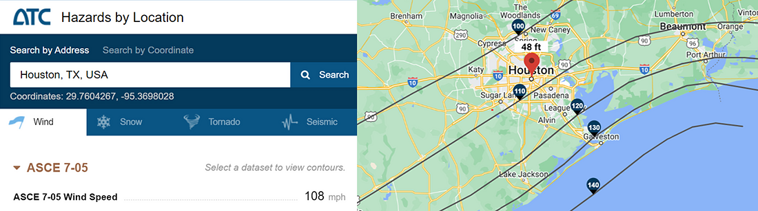
Step 6. AASHTO 2013 uses wind map ASCE 7-05. 108MPH is the wind speed.
Solution:
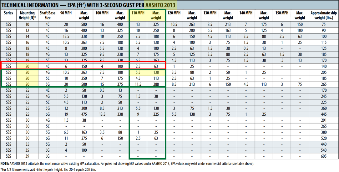
Based on the AASHTO 2013 table shown below, a 110MPH windspeed allows for a maximum EPA of 5.5ft² and a maximum weight of 138lbs for the SSS 20 4G, well over the summation of EPAft² and weight for a quantity of 2 DSX2 fixtures. The SSS 20 4C on the other hand, may meet the requirements for the EPAft² loading but it does not meet the weight requirement. SSS 20 4G is the correct selection.
Caution: This pole selection process is a guideline only. Acuity Brands assumes no responsibility for selection and recommends consultation with qualified individuals for verification of light fixture or pole assembly selection.
There are several job site conditions that do require special consideration and the specification sheet “Technical Information” tables do not account for. These conditions cause known excessive loading and include but not limited to:
- Projects that require Florida Building Code (FBC design criteria) or if the pole specification sheet does not have a “Technical Information” chart for the required design criteria
- Poles located near or on airport property
- Poles located on top of parking decks, bridges or catwalks
- Poles located in expansive, flat locations with few things to block wind
- Applications needing more than 3 festoons or handholes
- Catenary and cable systems applications *
- Banner arm applications *
Please contact Tech Support Outdoor if any of the above apply to your project or if you need help sizing a pole. The Wind Loading and Anchorage Verification form shown below will be required to effectively size a pole for these special considerations. Download the full form here.
* RFA required.

ASCE Wind Maps and Design Criteria
There are three main wind maps used for poles. There are other, newer wind maps from ASCE but, they are not often used for pole sizing and design.
- ASCE 7-93: Made in 1993, Wind speeds on this map are formulated using the least stringent method of measurement.
- ASCE 7-05: Made in 2005, Is quickly becoming the most commonly used wind speed map for poles.
- ASCE 7-10: Made in 2010, Becoming more common in high-risk, coastal areas and its method of wind speed calculation is the most stringent of the 3 listed here.
Use these ASCE Wind Maps to determine windspeed for your job site or visit the ASCE web page, where you can search by city and state to find windspeeds on a variety of wind maps.
Link: https://hazards.atcouncil.org/
For more information about Design Criteria, EPA, and Wind loading, check out this helpful presentation.. "How to Size a Pole - Design Criteria, Wind Speeds & EPA_100925" This breaks down all terms like ASCE, design criteria, loading forces and EPA. It discusses how they are related and why they are important to the pole selection process.
Steel poles are available in a wide variety of finishes. See below for various option.
Standard Finish for Steel Poles
Prime Painted Finish For Steel Poles
Finish Comparison for Steel Poles
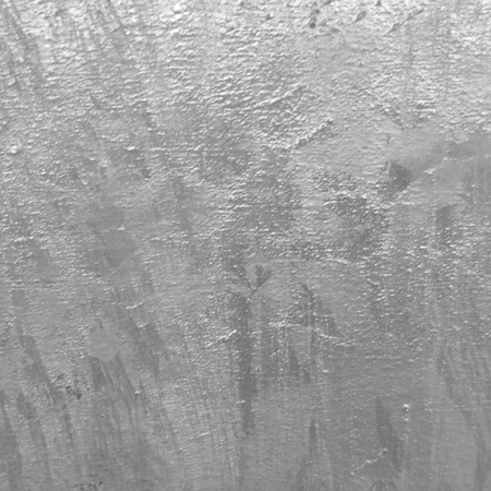
Galvanized Finish for Steel Poles
Paint Over Galvanized Finish for Steel Poles
Electro-deposition Coating Finish (E-coat)
Aluminum poles are lightweight, low maintenance and corrosion-resistant. They are available for both anchor base and direct burial installation. Aluminum poles are available in a wide variety of finishes.
Standard Finish for Aluminum Poles
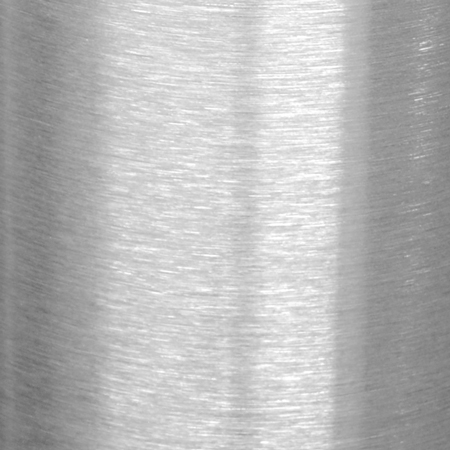
Brushed Finished for Aluminum Poles
Anodizing vs. Powder Coat Finishes
Hard Coat Anodizing
Fiberglass is corrosion-resistant and is available in a wide variety of colors as well as, a textured or smooth finish.
Standard Finish for Fiberglass Poles
Natural vs. Smooth Fiberglass Pole Finish
Laminated wood poles are available as natural or stained to enhance the natural wood finish.
Natural Finish for Standard Wood Poles
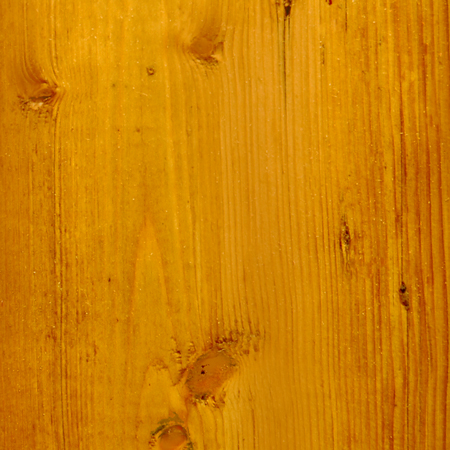
Stained Natural Wood Pole Finish
Standard Finish for Cedar Wood Poles